UAV Payloads #02
EO/IR Dual-Sensor Payloads: Why the Two Cameras Fall Out of Alignment
On a dual-sensor payload's display, the infrared hot spot is overlaid on the visible image, but it sits beside the person, offset by ten or so pixels.
The first reaction is usually "the alignment was not done properly". It is recalibrated, aligned perfectly at the ground test site, and drifts off again in flight.
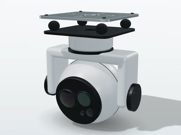
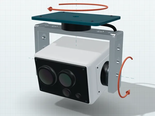
Usually this is not an alignment problem. The two cameras have two separate entrance pupils with a baseline between them, so physically they cannot coincide at every distance. This is geometry, not calibration quality.
1. Parallax: baseline divided by distance
With the entrance pupils of two cameras a distance b apart, both looking at a point at distance R, the angle between the two lines of sight is b ÷ R. If you align them at one distance during calibration, they drift apart at another, and the offset equals the difference between the parallax angles at the two distances.
| Target distance | Parallax angle | Residual after calibration at 122 m | EO pixel offset | IR pixel offset |
|---|---|---|---|---|
| 30 m | 1.333 mrad | 1.01 mrad | 10.5 px | 2.09 px |
| 122 m | 0.328 mrad | 0 (calibrated) | 0 px | 0 px |
| 500 m | 0.080 mrad | −0.25 mrad | 2.58 px (opposite) | 0.52 px (opposite) |
There are three common solutions, and none of them is "align more precisely":
- Shorten the baseline: squeeze the two cameras together. Halve the baseline and the parallax halves. The cost is mechanical space and heat dissipation, and longwave infrared lenses usually have sizeable apertures, so there is only so much room to squeeze.
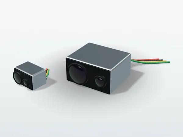
- Bring in distance information: estimate slant range from gimbal depression angle and altitude, or add a laser rangefinder, for real-time distance-dependent offset compensation. This is the proper solution, and one of the reasons tri-sensor payloads include an LRF.
- Do not overlay: show the two images side by side instead of fusing them. It sounds like dodging the issue, but in missions focused on interpretation it is often the most practical choice, because a wrong overlay misleads more easily than no overlay.
There are also common-aperture designs, where both bands share the same front optics and are then separated by a beam splitter, eliminating the baseline at its root; the cost is much higher optical complexity, weight and price, and they are less common on multirotors.
At a fire scene, "the hot spot marked beside the person" directly affects decisions. So if an overlay display does not take distance into account, it is better left off for close-range work.
2. Boresight alignment gets pulled off by temperature
Parallax is geometry; alignment residual is mechanics. Each camera is locked to a bracket, the bracket deforms when heated, and the relative angle between the two lines of sight moves with it.
To get a feel for the magnitude: with two mounting faces 60 mm apart, a relative displacement of 1 µm between them changes the angle by 1 ÷ 60000 = 16.7 µrad, already 0.17 of an EO pixel. Aluminum has a thermal expansion coefficient of 23 ppm/K, so a 60 mm structure grows 55 µm over a 40 K temperature change; if the expansion on the two sides is asymmetric by only about 10 % (5.76 µm), that is one EO pixel of boresight drift, and even 2 % asymmetry gives about 0.2 pixel.
What can be done: build the mounting datums for both cameras on the same piece of material and the same machined datum surface, so thermal deformation becomes common-mode rather than differential; avoid joining the two optical paths through adapters of different materials; and verify the boresight once at each end of the temperature range, not just at room temperature. The methodology here is the same as for production-line opto-mechanical systems; the full tolerance allocation approach is in Tolerance Allocation: Where Does Accuracy Leak Away?
3. Thermal defocus in germanium lenses is far worse than you think
Germanium is the most common lens material for longwave infrared. Its refractive index at 10 µm is 4.0032 and its thermal expansion coefficient 6 ppm/K, but its thermo-optic coefficient is as high as 396 ppm/K; ordinary optical glass is in the single digits, so germanium is almost two orders of magnitude higher.
The temperature coefficient of focal length for a single lens is:
(1/f)(df/dT) = α − (dn/dT) ÷ (n − 1)
Substituting: 6 − 396 ÷ (4.0032 − 1) = 6 − 131.9 = −125.9 ppm/K.
For a 25 mm lens and a 40 K temperature change (for example a housing that has baked in the sun on the ground and is then cooled by airflow after takeoff, or a payload whose required operating temperature range itself spans several tens of degrees; the 122 m altitude difference alone brings only about 1 °C of air temperature change), the focal length drifts by 126 µm.
And how large is the depth of focus? At f/1.0 with a permissible blur circle of one 12 µm pixel, the depth of focus is only ±12 µm. The drift is more than ten times the depth of focus. Worse, the aluminum housing is expanding at the same time, pushing the detector back by 23 µm over 40 K, in the opposite direction to the focal shift, for a total defocus of nearly 150 µm.
So infrared lenses with a wide operating temperature range must be athermalized (or use active focus compensation), with high-expansion spacers that move the lens group to compensate, or a hybrid design of germanium and chalcogenide glass whose temperature coefficients cancel each other out. A payload that skips this step slowly goes soft during flight, and room-temperature ground tests often fail to reveal it, because ground tests usually do not wait for the housing to heat through, and do not go through the airflow cooling after takeoff or the limits of the operating temperature range.
Incidentally, the Airy disk diameter at f/1.0 and a 10 µm wavelength is 2.44 × 10 × 1.0 = 24.4 µm, exactly two pixels: a longwave infrared system at f/1.0 is already close to the diffraction limit. Longwave infrared lenses are almost always made at f/1.0 to f/1.4, mainly because the NETD of an uncooled detector worsens roughly with the square of the f-number, so stopping down one stop halves thermal sensitivity; add diffraction, and there is no room to trade aperture for depth of field. For background on coatings, see Optical Coatings 101.
4. What longwave infrared can and cannot see through
This is the part most often misunderstood in the field. Longwave infrared wavelengths are 8 to 14 µm, twenty times longer than visible light, so scattering from "particles much smaller than the wavelength" is weak:
- Sees through: smoke. Smoke particles from combustion are mostly 0.1 to 1 µm in diameter, far smaller than the 10 µm wavelength, so scattering is weak and thermal imaging can see people and structures through dense smoke. This is the physical basis of firefighting applications.
- Cannot see through: condensed water mist. The white "steam" at a scene after water is sprayed is actually condensed droplets, comparable in size to the 10 µm wavelength, and liquid water also absorbs longwave infrared strongly, so the thermal image is blocked over large areas. Water vapor as a gas absorbs only weakly within the 8–14 µm window and mainly affects atmospheric attenuation over long distances. Many people assume thermal imaging can do anything, and then it fails at the very moment it is needed most.
- Cannot see through: glass. Ordinary glass is almost opaque in the longwave infrared; on a window you see the glass's own surface temperature and reflected ambient radiation, not the scene inside the room.
- Cannot see through: water. A water surface shows the surface temperature and the reflection of the sky, not what is underwater.
One more item: the fire itself saturates the image. Flame temperatures are far above the normal measurement range, so the area around the fire is overexposed and people nearby disappear into the white. Cores for firefighting therefore need high and low gain modes, with switching that can be locked manually, so that automatic gain does not jump on its own at a critical moment.
The measurement pitfalls, emissivity, reflected background and spatial resolution, are broken down in full in Why Do Thermal Cameras Misread Temperature? On an airborne platform there is one more: distance brings in atmospheric attenuation and path radiance, so absolute temperatures from airborne thermal imaging are for reference only, and judgments should rely mainly on relative temperature differences within the same image.
5. Cooled or uncooled
This decision is often framed first by the platform's weight and power budget, and only then by image quality.
| Item | Uncooled longwave infrared | Cooled midwave infrared |
|---|---|---|
| Power-up to usable | Seconds | Cooler cool-down, measured in minutes |
| Power consumption | About 0.5 – 1.5 W | Several times higher (a few watts at steady state, more during cool-down) |
| Range | Shorter | Longer, with better sensitivity |
| Life and maintenance | No moving parts, apart from the calibration shutter on some models | The cooler has a defined cumulative operating life |
| Gas detection | Mostly unsuitable; a few models detect specific gases with narrowband filters | Can match characteristic absorption bands (CO₂ 4.3 µm, CH₄ 3.3 µm) |
In most cases the conclusion is: use uncooled longwave infrared for general inspection, search and rescue and surveillance missions, because instant start-up, low power and low maintenance are all hard requirements on a UAV. Unless the mission clearly needs longer range or gas signature detection, the weight, power and maintenance costs of a cooled camera are hard to justify on a multirotor. The full band comparison table is in the infrared band reference.
6. Six things to do at acceptance
- Verify the boresight at two distances: once at close range and once at mission range, measuring the parallax and recording it in the documentation, rather than checking one distance and declaring it aligned.
- Re-verify after temperature cycling: confirm boresight and focus once at each end of the operating temperature range.
- Look at the image only after it has heated through: the housing often needs 20 to 30 minutes or more to reach thermal equilibrium (depending on model and environment), and images right after power-up cannot be used for acceptance.
- Check gain switching behavior: when a hot target enters the image, does automatic gain suppress other areas, and can it be locked manually?
- Measure the real video latency: film a stopwatch or a flash source and measure the total delay from the event to the ground station display, rather than trusting the core latency on the datasheet.
- Decide whether to keep raw data: if later reanalysis is needed, a compressed stream cannot recover it; to keep raw radiometric data, room has to be left in the board and storage specifications from the start.