Optoelectronics Basics #03
Optical Coatings 101: Why Do Lenses Look Purple?
Hold a camera lens up to the light and its surfaces reflect a faint purple, blue-green or amber. That is not the color of the glass, and it is not there for looks: it is the trace of a coating only a few hundred nanometers thick, and that layer may be the most critical technology in the whole lens.
This article explains what coatings do, why they have color, and how choosing the wrong coating design can make an entire optoelectronic system fail. The first article in this series, What Is Optoelectronics?, gives an overview of the field; if you have not read it yet, you may want to start there.
1. First, how much is lost without a coating
When light passes from air into glass, part of it is reflected at the interface. At normal incidence the reflectance is given by the Fresnel equation:
R = ( (n₁ − n₂) / (n₁ + n₂) )²
Air n₁ = 1.00, common optical glass n₂ = 1.52:
R = ( (1.00 − 1.52) / (1.00 + 1.52) )² = 4.26 %
A piece of glass has two surfaces, so a single piece loses about 8.3 %. The problem is that a lens has more than one element:
| Optical surfaces | Equivalent to | Transmission |
|---|---|---|
| 2 | A single flat plate | 91.7 % |
| 4 | Two lens elements | 84.0 % |
| 8 | Four lens elements | 70.6 % |
| 12 | A six-element lens group (typical of a prime lens; zoom lenses often have more than ten elements) | 59.3 % |
With a six-element group, less than 60 % of the light gets through. And most of the lost 40 % is reflected light, part of which bounces back and forth between elements before reaching the sensor as ghosting and flare: for an uncoated six-element group, this secondary reflected light can be on the order of 10 % of the image-forming light, enough to noticeably reduce contrast in the shadows.
Coatings solve not just brightness but contrast. Most of the lost 40 % is reflected out of the front of the lens, but the stray light on the order of 10 % that lands on the sensor often does more harm to the image than losing 40 % of the brightness: it lifts the shadows directly and eats away the contrast.
2. How anti-reflection coatings make reflection disappear
Anti-reflection (AR) coatings use destructive interference. A thin transparent film is deposited on the glass surface so that light is reflected once at the air/film interface and once at the film/glass interface, and the two reflected beams are made half a wavelength out of phase so they cancel each other.
2.1 How thick the film must be
In a film with refractive index n, the wavelength of light shortens to λ/n, so the physical thickness of a quarter wavelength is λ / 4n. Taking the most common material, magnesium fluoride (MgF₂, n = 1.38), as an example:
- Design wavelength 550 nm (middle of the visible) → film thickness 100 nm
- Design wavelength 1064 nm (Nd:YAG laser) → film thickness 193 nm
- Design wavelength 1550 nm (fiber-optic communication) → film thickness 281 nm
A thickness on the order of a hundred nanometers, and it has to be uniform over the whole curved lens surface: that is the real difficulty of the coating process.
2.2 What refractive index the film needs
For the two reflected beams to cancel completely, besides being in antiphase, their amplitudes must be equal. The derivation shows that the ideal film index is the square root of the substrate index:
nideal = √nglass = √1.52 = 1.233
Here is the problem: nature offers no durable material with an index that low. MgF₂ at 1.38 is already among the lowest practical materials, and a single layer of it leaves a residual reflection at the design wavelength of:
R = ( (nfilm² − nglass) / (nfilm² + nglass) )² = 1.26 %
From 4.26 % down to 1.26 % is an improvement of about 3.4 times: already very useful, but not zero. To go lower you have to stack multiple layers, alternating high- and low-index materials so that several reflected beams cancel each other. Modern multilayer broadband AR coatings can keep reflection below 0.5 % across the whole visible range, and good narrowband designs can even reach 0.1 %.
3. So why purple?
The key is that there is only one "design wavelength". Once the film thickness is fixed, destructive interference is perfect only at that one wavelength, and the further you move from it, the weaker the effect.
Lens coatings usually put the design wavelength at green in the middle of the visible range (around 550 nm), because that is where the eye is most sensitive and where the image matters most. The result:
- Green light: cancelled most thoroughly, hardly reflected at all
- Red and blue light: further from the design wavelength, with more residual reflection
With green missing from the reflected light, what remains is red plus blue, which together look purple. So the purple reflection of a lens is not a deliberate tint; it is the result of "green being swallowed".
Coating designs differ between manufacturers: a design wavelength shifted toward blue looks amber, while multilayer broadband coatings have fainter, more mixed colors. The color of a coating gives a rough idea of which band its design focuses on, which is also why infrared lens coatings often look golden or deep blue: their design wavelength is not in the visible at all.
4. Not just anti-reflection: reflective coatings and filters
The same multilayer interference principle, with a different design goal, gives completely different components.
| Coating type | Goal | Typical uses |
|---|---|---|
| Anti-reflection (AR) | Minimize reflection | Lenses, windows, sensor cover glass |
| High-reflection (HR) | Reflection close to 100 % | Laser resonators, mirrors, scanning galvo mirrors |
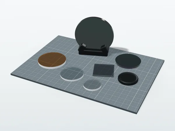
| Bandpass filter | Pass only a specific band; most other wavelengths are reflected | Fluorescence measurement, gas detection, multispectral imaging |
Dielectric high-reflection coatings can exceed 99.9 % reflectance with almost no absorption, something metal coatings cannot do (aluminum mirrors are about 90 %, silver about 97 % but it oxidizes). Laser resonators usually need dielectric coatings: light inside the cavity makes many round trips between the two mirrors, a loss of a few percent per pass makes it hard for the laser to start oscillating, and the few percent a metal coating absorbs is enough to burn the coating at high power.
Bandpass filters are the core component of multispectral measurement. To detect a specific gas, the filter's passband is aligned with the gas's characteristic absorption wavelength: SWIR judging moisture content at 1.45 µm and MWIR detecting hydrocarbons at 3.3 µm both rely on filters blocking the other wavelengths.
5. Coatings in the infrared are a different matter altogether
Experience with visible coatings does not carry over directly to the infrared, because even the substrates are different. Ordinary optical glass stops transmitting above 2.5 µm, so infrared systems use:
- Silicon (Si): SWIR to MWIR, with a refractive index as high as 3.4
- Germanium (Ge): MWIR to LWIR, refractive index 4.0
- Zinc selenide (ZnSe): broadband and also transparent in the visible, often used for CO₂ lasers
For germanium with an index of 4.0, the uncoated single-surface reflectance is:
R = ( (1 − 4.0) / (1 + 4.0) )² = 36 %
For a germanium window, with both surfaces and the multiple reflections between them taken into account, transmission is only about 47 %: more than half the light does not get through. So for infrared optics it is not that "coated is better"; without a coating they are hardly usable. After three germanium lenses and six surfaces, transmission is down to about 10 %.
In addition, germanium is hard (Knoop hardness about 780) but brittle, while zinc selenide is much softer (about 120) and scratches easily. Germanium windows for outdoor or industrial environments often get an extra DLC (diamond-like carbon) protective coating, which combines scratch resistance, moisture protection and anti-reflection; zinc selenide is mostly used in protected, unexposed positions.
6. What happens if you choose the wrong coating
In system integration, coatings are easily treated as "something that comes with the lens", but their failure modes are very direct:
- Wrong working band: a window with a visible AR coating used in a 1550 nm laser system may reflect more than an uncoated one, and the light reflected back into the laser cavity causes instability
- Wrong angle of incidence: coating designs depend on angle, and as the angle of incidence increases the passband shifts toward shorter wavelengths. For wide-field lenses or scanning systems, this has to be built into the design from the start
- Wrong environmental conditions: in high humidity, salt fog or frequent temperature cycling, coatings peel or fog. What matters here are the durability specifications of the coating (adhesion, damp heat and salt fog tests), not its optical performance
- Insufficient laser damage threshold: coatings for high-power laser systems must state an LIDT; choose wrong and the coating gets burned through
What these problems have in common is that at the purchasing stage they are one field in a specification, and at the system integration stage they are a fault that is very hard to trace. A failed coating usually does not stop the system working altogether; it just makes the signal-to-noise ratio inexplicably poor, or the stray light inexplicably high.
Closing: a few hundred nanometers decide the whole system
Coatings are a classic case in optoelectronic systems: a small share of the cost and a low profile, yet they decide how much light actually reaches the sensor. Spending half a day confirming coating specifications during system design is far cheaper than spending two weeks afterwards working out why the contrast is not good enough.
The next time you see that purple reflection on a lens, remember what it means: the green light has already been sent in; this is just what is left over.